ADT7518
Rev. A | Page 11 of 40
DAC-to-DAC Crosstalk
This is the glitch impulse transferred to the output of one DAC
due to a digital code change and subsequent output change of
another DAC. This includes both digital and analog crosstalk. It
is measured by loading one of the DACs with a full-scale code
change (all 0s to all 1s and vice versa) with
LDAC
low and
monitoring the output of another DAC. The energy of the glitch
is expressed in nV-s.
Multiplying Bandwidth
The amplifiers within the DAC have a finite bandwidth. The
multiplying bandwidth is a measure of this. A sine wave on the
reference (with full-scale code loaded to the DAC) appears on
the output. The multiplying bandwidth is the frequency at
which the output amplitude falls to 3 dB below the input.
Total Harmonic Distortion
This is the difference between an ideal sine wave and its atten-
uated version using the DAC. The sine wave is used as the
reference for the DAC, and the THD is a measure of the
harmonics present on the DAC output, expressed in dB.
Round Robin
This term is used to describe the ADT7518 cycling through the
available measurement channels in sequence, taking a measure-
ment on each channel.
DAC Output Settling Time
This is the time required, following a prescribed data change, for
the output of a DAC to reach and remain within ?.5 LSB of the
final value. A typical prescribed change is from 1/4 scale to
3/4 scale.
AMPLIFIER
FOOTROOM
LOWER
DEADBAND
CODES
NEGATIVE
OFFSET
ERROR
GAIN ERROR
+
OFFSET ERROR
ACTUAL
OUTPUT
VOLTAGE
NEGATIVE
OFFSET
ERROR
DAC CODE
IDEAL
Figure 8. DAC Transfer Function with Negative Offset
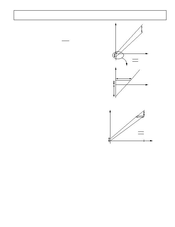
ACTUAL
GAIN ERROR
+
OFFSET ERROR
UPPER
DEADBAND
CODES
OUTPUT
VOLTAGE
POSITIVE
OFFSET
ERROR
DAC CODE
FULL SCALE
IDEAL
Figure 9. DAC Transfer Function with Positive Offset (V
REF
= V
DD
)
发布紧急采购,3分钟左右您将得到回复。
相关PDF资料
AT30TS00-MAH-T
SENSOR DGTL TEMP I2C/SMBUS 8WDFN
AT30TSE002B-MAH-T
SENSOR DGTL TEMP I2C/SMBUS 8WDFN
BD3504FVM-TR
IC REG CTRLR SGL POS ADJ 8MSOP
BD3521FVM-TR
IC REG CTRLR SGL 1.5V MSOP8
BD9153MUV-E2
IC REG TRPL BCK/LINEAR 24VQFN
CAT2300VP2-GT3
IC SENSE FET CONTROLLER 8TDFN
CAT34TS02VP2GT4A
IC TEMP SENSOR 2K MEMORY 8TDFN
CAT6095VP2-GT4
IC TEMP SENSOR STAND ALONE 8TDFN
相关代理商/技术参数
ADT7518ARQZ-REEL
制造商:Analog Devices 功能描述:Temp Sensor Analog Serial (4-Wire, SPI, I2C) 16-Pin QSOP T/R
ADT7518ARQZ-REEL7
制造商:Analog Devices 功能描述:Temp Sensor Analog Serial (4-Wire, SPI, I2C) 16-Pin QSOP T/R
ADT7519
制造商:AD 制造商全称:Analog Devices 功能描述:SPI-/I2C-Compatible, Temperature Sensor,4-Channel ADC and Quad Voltage Output
ADT7519ARQ
制造商:Analog Devices 功能描述:Temp Sensor Digital Serial (4-Wire, SPI, I2C) 16-Pin QSOP
ADT7519ARQ-REEL
制造商:Analog Devices 功能描述:Temp Sensor Digital Serial (4-Wire, SPI, I2C) 16-Pin QSOP T/R
ADT7519ARQ-REEL7
制造商:Analog Devices 功能描述:Temp Sensor Digital Serial (4-Wire, SPI, I2C) 16-Pin QSOP T/R 制造商:Analog Devices 功能描述:TEMP SENSOR DGTL SERL (4-WIRE, SPI) 16QSOP - Tape and Reel
ADT7519ARQZ
功能描述:IC TEMP SNSR QUAD DAC 16-QSOP RoHS:是 类别:集成电路 (IC) >> PMIC - 热管理 系列:- 标准包装:3,000 系列:- 功能:温度开关 传感器类型:内部 感应温度:85°C 分界点 精确度:±6°C(最小值) 拓扑:ADC(三角积分型),比较器,寄存器库 输出类型:开路漏极 输出警报:是 输出风扇:是 电源电压:2.7 V ~ 5.5 V 工作温度:-55°C ~ 125°C 安装类型:表面贴装 封装/外壳:SC-74A,SOT-753 供应商设备封装:SOT-23-5 包装:带卷 (TR) 其它名称:ADT6501SRJZP085RL7-ND
ADT7519ARQZ1
制造商:AD 制造商全称:Analog Devices 功能描述:SPI/I2C Compatible, Temperature Sensor, Four Channel ADC and Quad Voltage Output DAC
